Creating an antenna
This chapter will describe how to create an antenna, detailing the tape strips, burnwire and brackets placement, along with the antenna tuning.
What you need
-
3M DP2216 epoxy or similar, with apply gun;
-
Cardboard/PVC tube, with around 1 meter;
-
Velcro tape with adhesive;
-
u.FL male cable;
-
Dremel tool;
-
Soldering iron and solder;
-
Cutting and drilling pliers;
-
Sandpaper;
Step 1: Prepare and place the tape
-
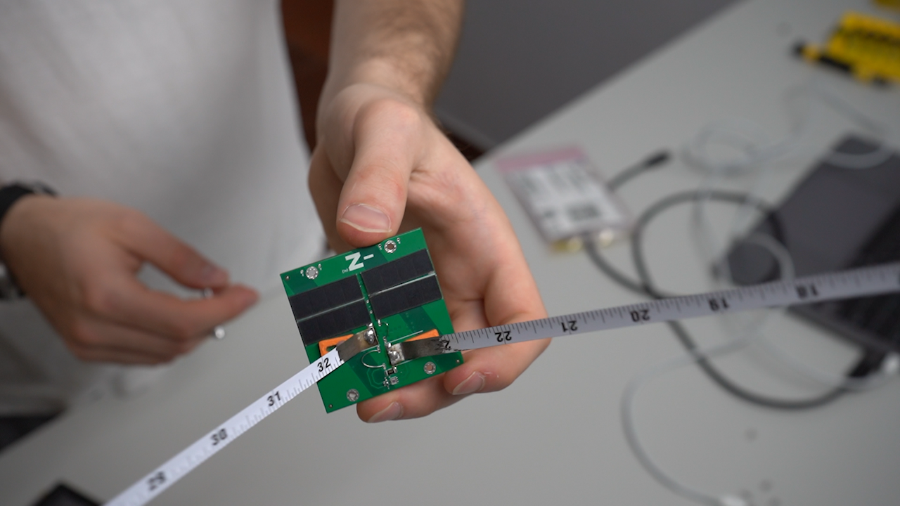
Grab the referenced tape measure, get it out of the rolling box and cut at least two strips of around 20 cm each, making sure they are the same size;
-
With a Dremel tool, remove around 3 cm from one of the sides of each strip to create an electrically conductive and solderable region;
TIP: be extremely precise in removing all the paint around the edge to improve solderability.
-
At the recently scraped region, from about 1 cm of the tip, bend the strip 90 degrees to form a crease;
-
Solder the creased tips of two strips to the antenna pads on the -Z board.
NOTE: the soldering step must happen right after the scraping and bending due to oxidation issues on the strip.
Step 2: Prepare and place the burn wire
-
Cut at least two burn wire pieces of aroung 3 cm each;
-
Pass them through the specified holes, keeping the center of the wire, and the majority of its length, on the same side of the antenna strips;
-
On the other side, bent the necessary to keep it in place, solder both contact points and cut the excedent wire.
Step 3: Attach the antenna brackets
-
After printing the brackets, place each between the antenna and the board, with the inclination touching the strip and its openings matching the board holes;
-
Place a M2 nylon screw from the top through the bracket opening and the board hole, securing it with a corresponding nylon nut on the bottom side;
Step 4: Tune the antenna
- Grab a 1 m cardboard/PVC tube and place the antenna board on one end and the VNA on the other, with velcro tape with adhesive, and connect the two (an adapter from u.FL to SMA connectors may be needed);
NOTE: the tube creates a safe distance between the parts, in terms of eletromagnetic interference
-
With the VNA, measure the initial frequency, resistance and reactance of the antenna. The desired values are around 433 MHz, 50 Ω and 0 Ω, respectively.
-
Disconnect the antenna from the VNA;
-
For tuning the frequency, since it has an initial value below the desired, cut around 5 mm in each strip;
-
Connect the antenna again and check the frequency;
TIP: each 5 mm cut should decrease in aroung 10 MHz, however it is still recommended to cut that size at a time and remeasure
-
Repeat the last three points until the value is close to the desired, then reducing the cutting size to only 1 mm (or less);
-
For tuning the reactance, adjust the position of the brackets by sliding them. Overall, widing the antenna will increase its reactance, narrowing will decrease it;
Step 5: Final procedures
-
Make sure you achieved the desired antenna parameters before proceeding;
-
Make a 1 mm in diameter hole on the center of the outter edge (about 3 mm from the tip) of the antenna strips with a hole punch pliers, and sand it;
-
Apply a good amount of epoxy on the sides of the brackets to fix it in position. Make sure the epoxy does not escape the board surface, neither touches the antenna strip or the nylon screw;
-
Leave the board in a safe place to dry for about a day, and later remove the nylon pieces.
Video guide
Press on the image to be redirected to view the video guide on YouTube.