LoRa communication
Another test that can be performed is the correct sending or receiving of LoRa packets. This can only be achieved while main board and antenna (-Z) board are connected, which is extremely important, since the absence of an antenna (load) may damage the trasmitter due to wave (power) reflection implying voltage and current overloads [1].
The test software is released in Tests, and is already built. To fully test, a second device is needed to check if the satellite is either able to successfully send of receive the packets. It can be another satellite (with both using the same test files) or a groundstation, composed of a ESP-32 or Raspberry Pi microcontroller with a compatible LoRa chip.
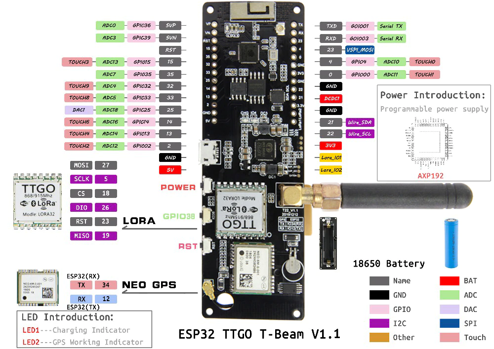
During testing phase, we had all the options stated: LILYGO® TTGO T-Beam v1.1, a ESP-32 based groundstation; and RExLab custom groundstation, RPi based; and another twin satellite. We will cover the first case since it can be more easily replicated, either with a similar designed board or just with a simple ESP-32/Arduino connected to a LoRa IC.
What you need
-
Mu Editor and Arduino IDE;
-
Lora Radio Range Test files;
-
Main and -Z board;
-
u.FL male to u.FL male cable;
-
USB-C cable, with power and data lines;
-
Another LoRa device for validation;
Step 1: Configure the groundstation for sending
-
After installing Arduino IDE, install the ESP32 board drivers (follow this tutorial). In our case, the board reference changes to 'TTGO LoRa32-OLED' and the COM port may be defined to another instance;
-
Install the libraries needed for peripherals, such as the OLED and LoRa chip (follow this tutorial);
-
Create a project with the sender sketch from the last tutorial, compile, run and open Serial Viewer, configured with the correct parameters. Again, in our case, change the board pins (MISO, SDA, ...) to the correct board pinout and frequency (433 MHz);
-
The OLED should display the init prompt and the board starting to send packets.

Step 2: Set the satellite for receiving
-
Connect the main and -Z boards with the u.FL cable;
-
Like the previous unitary test, copy the files to the mainboard, open Mu Editor serial console and start running the program (CTRL+D);
-
Follow the serial prompt, selecting the satellite option, followed by the radio parameters change (the default options should be fine);
-
Finally, you should set the receiving mode with acknowledge;
-
In a few seconds, it should print the received LoRa packet info, such as the RSSI and the message;

Step 3: Invert the communication direction
To make the groundstation for Rx mode, you can simply use the receiver sketch instead of the sender one, also released in the previous tutorial website and switch the satellite to Tx mode on prompt.