Flash SAMD UF2 bootloader on mainboard
Based on RExLab tutorial:
The following procedure needs to be performed only once (barring any bricking / updating the bootloader) on a newly assembled mainboard with an unprogrammed MCU - in our case, the ATSAMD51J19A.
What you need
ATSAMD51 board (such as the PyCubed-Mini mainboard);
Windows PC with atleast 2 free USB ports;
SEGGER J-Link (we use the EDU Mini model);
2x5 pin 1.27mm pitch ribbon cable;
USB-C and micro-USB cables, both with power and data lines;
SAMD bootloader binary file.
Step 1: Set up your PC
Visit Microchip Studio download page, scroll down, and download the Web installer version of Microchip Studio. (The offline installer should also work, however I have had issues with antivirus software blocking it);
Accept the Terms and Conditions, and deselect the "Send anonymous data" box. On the next page, select the architectures you'd like to install - we will only be using SAM boards. Finally, deselect "Advanced Software Framework and Example Projects" as these are not necessary. The rest of the installation should be fairly straightforward;
If asked to install the XC8 compiler, simply hit "OK" without installing - it is not necessary for this guide;
Microchip Studio should now be set up and open;
Next, visit SEGGER J-Link download page, and download the latest Windows version of the J-Link software. The install process for this is fairly straightforward. The default settings should work fine;
A new SEGGER J-Link DLL Updater window will open asking to update Atmel Studio to the latest SEGGER software version. Make sure the check mark is selected and click "OK";
Your computer is now ready for flashing the bootloader.
Step 2: Flash the bootloader
-
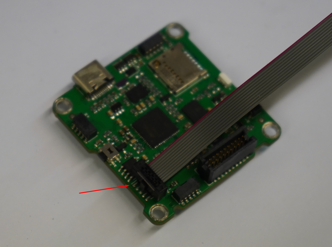
Plug one end of the ribbon cable on 2x5 connector of the main board. Make sure pin 1 of the ribbon cable (red wire) is matching pin 1 of the board connector (longer silkscreen mark);
-
Plug the other end on the J-Link. Make sure pin 1 of the ribbon cable is matching pin 1 of the connector (white dot);
-
Plug the J-Link on your PC with the micro-USB cable;
-
Plug the the main board on your PC with the USB-C cable;
Based on AdaFruit tutorial:
Next, open Atmel Studio. From the toolbar, select "Tools" -> "Device Programming";
The device programming window will open. Then, select "Tool" -> "J-Link";
If you're using a J-Link EDU, accept the terms of use that will pop up after selecting the J-Link interface;
After that, select the Device (the type of chip you're programming): ATSAMD51J19A and click "Read" in the top navigation bar. The empty fields for Device Signature and Target Voltage should populate;
NOTE: Make sure these values appear before proceeding! If the board or your wiring is not detected, Atmel Studio will throw an error that it could not connect to the board. Check your wiring and try to connect again.
On the sidebar, click Memories. On Flash, select the bootloader binary file that you either built or downloaded, and mark "Erase Flash before programming";
Click "Program", then "Verify";
NOTE: After clicking, the serial should output "OK" for each action, and there should be a new USB volume mounted on your machine.