Printed Circuit Boards (PCBs)
The PCBs are the fundamental hardware of the PyCubed-Mini, as they are precisely designed to hold its required components, as well as their connections, being that external, with USB-C connectors to easily interface with a computer or internal ones: between components in the same board, through the middle of it; or between board with stack connectors, with data and power lines.
The satellite is composed of eleven PCBs in total: five horizontally stacked inside, one on top of the other; and six covering each outside face of the cube. The KiCad schematics and board designs, as well as the gerber files for each are released in Boards. There are some components which require its schematic, footprint and CAD model to be imported to the KiCad project libraries to be fully recognized. To do so, please follow the official KiCad documentation.
The recommended manufacturing option is to print the boards and solder the components at specialized companies, since there are multiple components in each board, some of them with different maximum temperature, in very reduced size or in need of a reflow oven.
This section will only mention the primary components and their references, discarding stack connectors and power regulation (present in all), reset and boot switches and status LEDs (present in some).
Inside boards
The first group is divided in main board, camera board and battery boards.
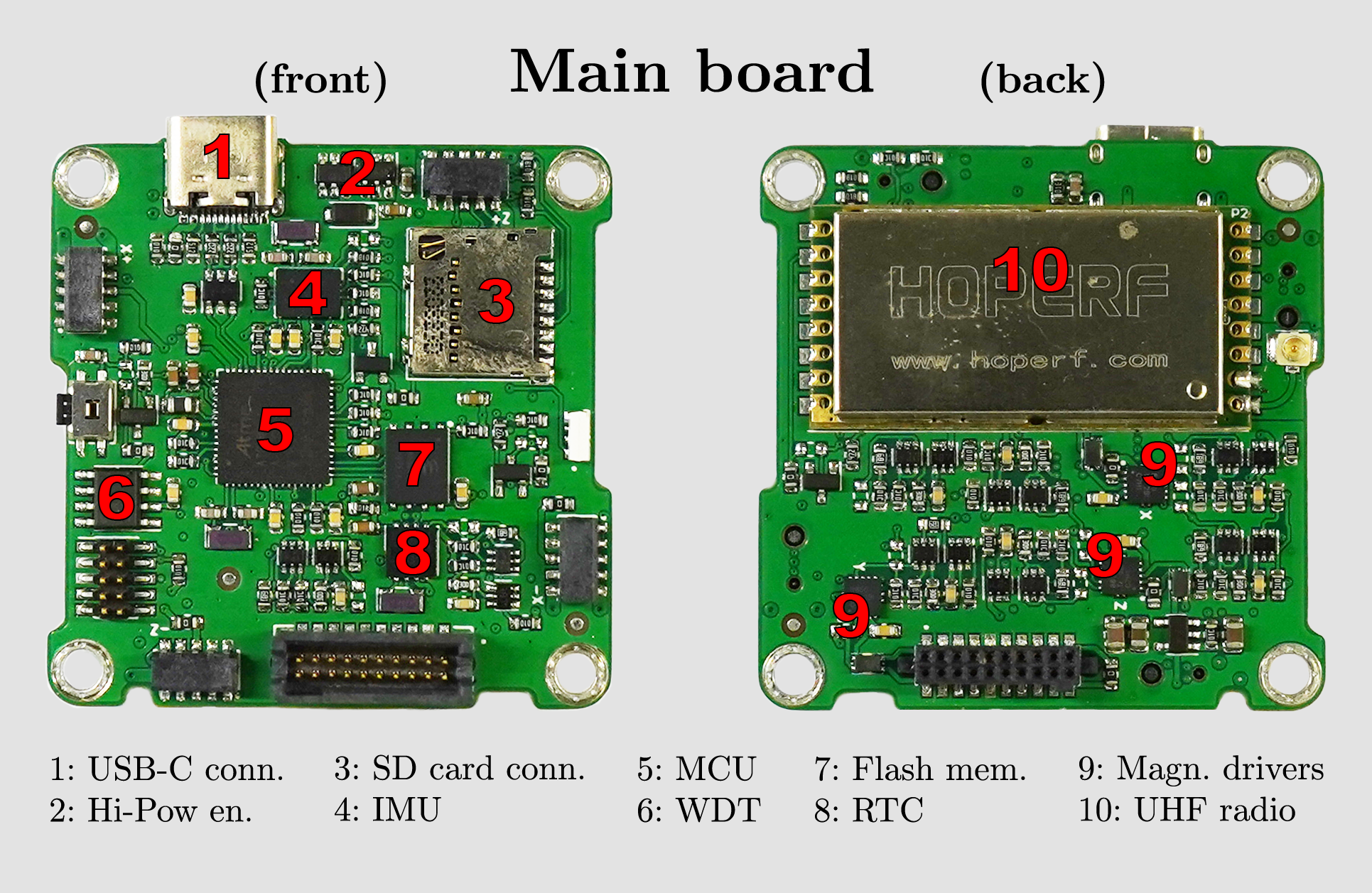
Main board
The main board contains the ATSAMD51J19A main microcontroller and MAX706 external watchdog timer, BNO085 IMU sensor and magnetorquer drivers, PCF8523 Real Time Clock, RFM98 radio module for 433 MHz LoRa communication, a USB-C connector for side power, flashing and communicating and SD Card connector for data logging.
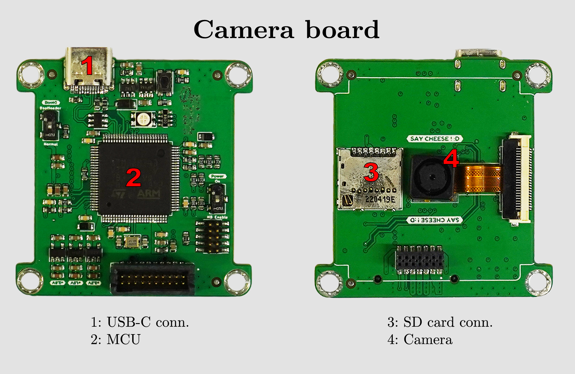
Camera board
The camera board, as the name tells, holds the OV5640 camera, the STM32H743VI camera microcontroller, an SD Card connector for image savings, and a USB-C connector, for the same reasons as the main board. The camera ribbon cable is placed on the desired connector and should be fixed in the center square with tiny quantities of epoxy.
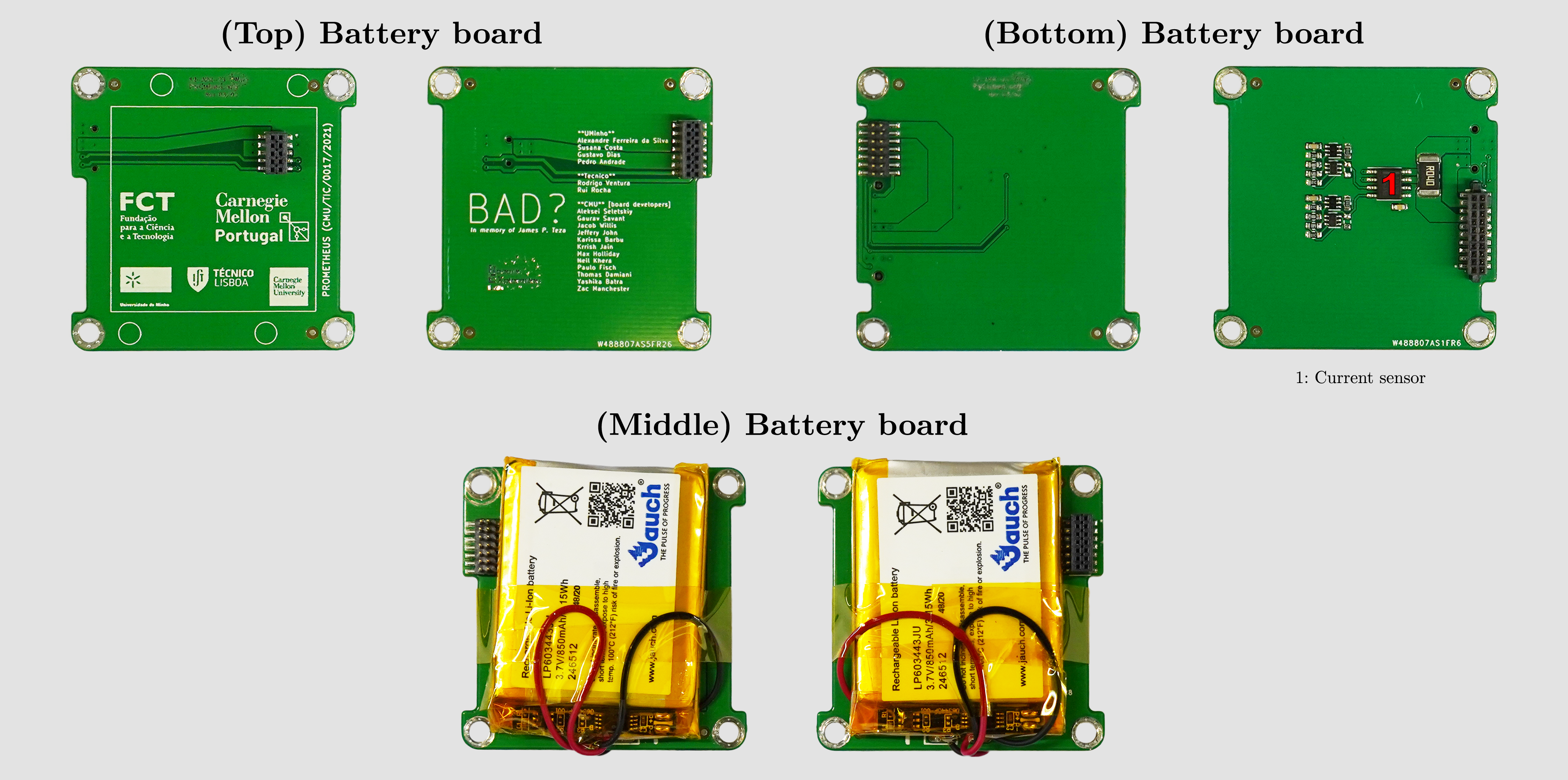
Battery boards
Two LP603443 batteries present in the satellite are placed between the three battery boards, wired in parallel for improved capacity, each with 3.7 V and 3.15 Wh. The circuitry is capable of sensing the current drawn and measuring its voltage.
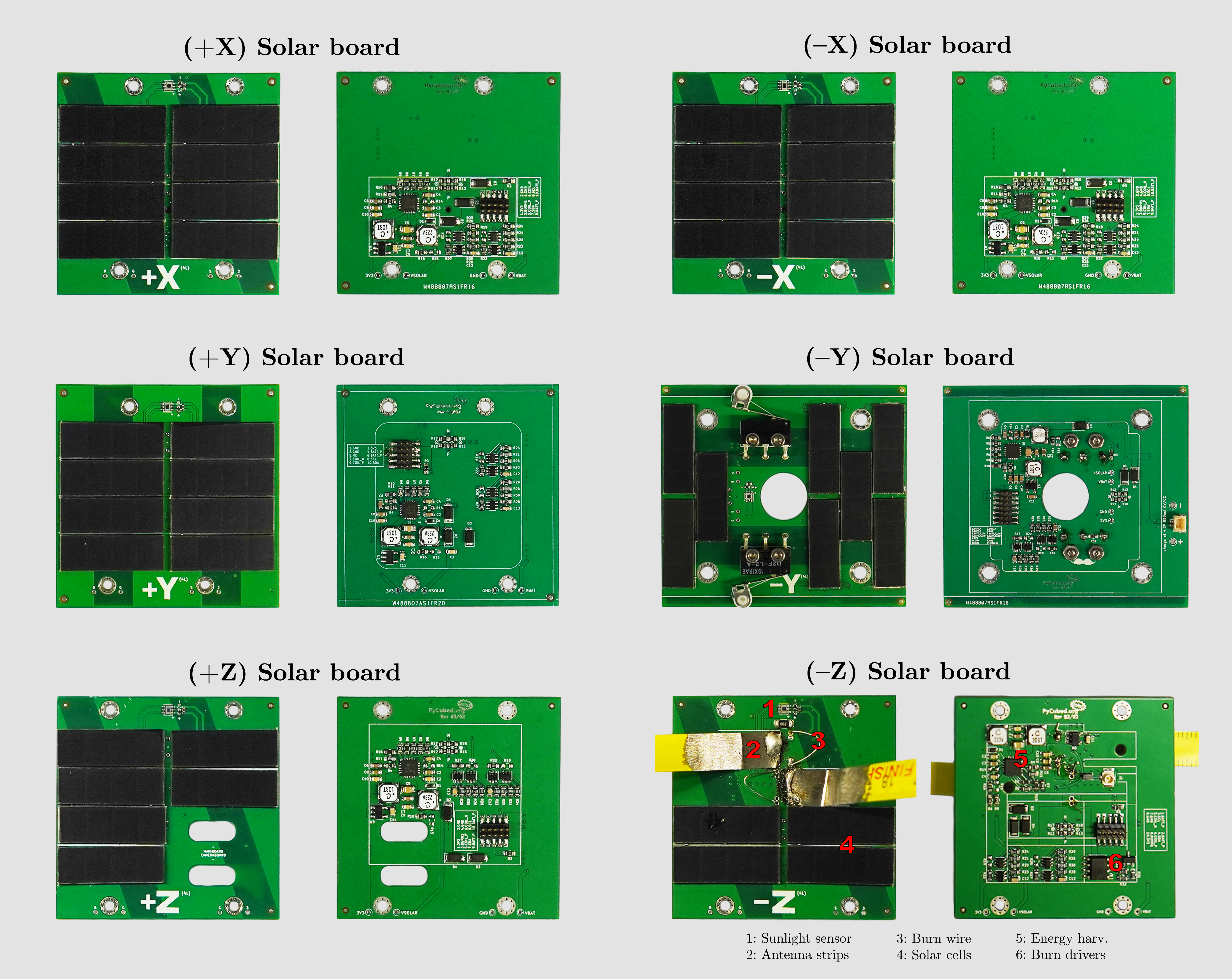
Outside boards
In all six solar boards (Figure 7), there are 14-turn coils serving as magnetorquers, 42 solar cells (KXOB25-05X3F) spread by the available space, energy harvesting systems, as well as OPT3001 sunlight sensors. There is also the antenna and burn wires, for its deployment, in one of the faces. Also, at the bottom one, there are two position switches that cut the battery power when pressed, preventing power draining during testing and storing. It has also a hole in the center, enabling the camera to take visible pictures.
In all solar boards, there is a 0 Ω resistor that is responsible for defining the correct I2C bus assignment. For negative axis boards, this SMD type wire pulls the I2C line to ground, while in positive boards, it should pull to power.

You can also check some important voltage potential values, such as (B)attery, (G)roud, (S)olar panels and (3).3 V, in the holes near the board edges.
+X, -X, +Y boards
These boards are equal, composed of eight solar cells each.
-Y board
This board, besides the eight solar cells, holds two position switches that cut the battery power when pressed, preventing power draining during testing and storing. It has also a hole in the center, enabling the camera to take pictures.
+Z board
This board holds the two holes needed for the USB-C connectors in main and camera boards, besides the six solar cells.
-Z board
This board, besides the four solar cells, holds the antenna, which is holded in place with fishing line tied to each burn wire.